
| Three
basic types of ways exist: plain sliding, rolling element and
hydrostatic ways. The plain sliding way, the oldest type, remains in
common use. In this design, the moving surfaces slide against each
other assisted by a layer of lubrication which, when operating
correctly, actually produces a hydro-dynamic bearing. That is a bearing
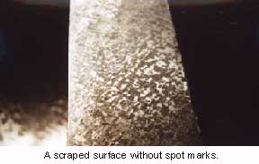
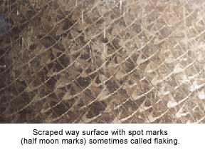
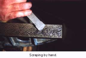
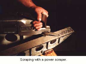
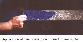
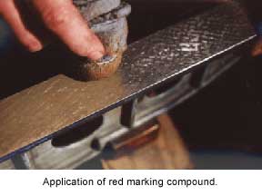
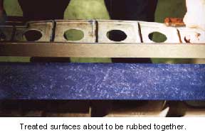
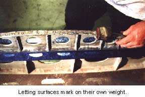
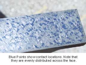
which guides on a controlled layer of lubrication created by motion. The Way Ways Were The first machine tools for cutting iron used wooden ways, but by the mid 19th century, cast iron became the material of choice for machine elements. It had the advantage of easy formability. Builders could produce it into shapes, cut it with the single point tooling of the time and hand fit it with a scraping operation. Few other options existed. When two scraped cast iron surfaces meet with a layer of oil in between, they slide rather well. For 100 years cast iron to cast iron plain slide ways were the state-of-the-art in way design. There is a good deal of art in the production of cast iron way surfaces. Historically, plain ways represented an important part of the value added by a machine tool builder. A highly skilled trade called "hand scraping" was, and still is, necessary to properly fit cast iron way surfaces and make a machine both geometrically correct and long lasting. But for years machine tool builders have tried to eliminate this labor-intensive manual scraping process. Match milling or grinding has only been marginally successful. In most cases, builders can machine the longer guiding surfaces, but the fitting of the mating component still requires scraping. In fact, the cost, time and skill involved in scraping plain ways have been major factors in the current move to rolling element linear way systems. Today, many machine manufacturers purchase some type of rolling element linear guide. This reduces cost of entry for new builders because the linear guide "erector set" assembly eliminates the need to scrape. Why scrape? Plain bearings do offer important advantages over rolling elements and so scraping lives on. The scraping procedure attempts to spread the points of bearing contact evenly across the whole bearing face, while achieving the correct geometric alignments. In fitting a way, workers identify points of contact by applying thin coats of marking compounds to both surfaces. After sliding the surfaces against each other for about an inch, the technician removes the slide and examines the bearing points left in the marking compound. A common standard is ten to fifteen points in any one square inch of bearing area. It is possible, and to a certain extent desirable, to achieve forty or more points with repeated fine scrapings. Whether the count reaches ten points per inch or forty, the percentage of area in contact should be 50 to 60 percent. The spaces between high and low points provide oil reservoirs important to accuracy and long life. When bearing contact exceeds 80 percent there is an effect similar to the ringing together of joe-blocks resulting in "stick-slip" effects. Thousands of high and low spots in a scraped surface provide evenly distributed oil reservoirs, and drains. As motion starts, oil is dragged between high spots across the whole surface. Perfectly flat surfaces ( 100 % ) at rest would with time squeeze out all oil and ring together. As this “sticktion” is overcome, the slide must move the distance between oil grooves to become lubricated. At that point, the slide rides up on a hydroplane of oil without the draining effects of the low spots in the scraped surface (like the thread of a tire), the slide rises up several thousandths causing inaccuracies. Breaking up a bearing surface with a power spotter, which leaves a series of half moon shaped marks on the ways, provides a quick fix for this problem. These spot or flaking marks are not to be confused with scraping. Developed as a cosmetic treatment, the marks give the surface a uniform appearance. Today, spotting provides relief in bearing surfaces that have lapped themselves flat by wearing through their relief. Spotting will not improve the straightness or flatness of a way surface, but it will help with stick-slip problems. Scraping is the only way to sculpt flat straight surfaces in cast iron that make contact evenly across the whole length and width of their mating surfaces. For instance, if a vee and flat way were not at the exact height and angle with respect to each other, one edge of the flat would hit the bed ways causing the load to be focused on that area. Then the oil layer would breakdown and spalling, scoring or uneven wear would occur. In other words, unless the technician does the hand scraping correctly, the slides are not likely to have a long life. To overcome the problem of spalling and scoring, builders introduce other bearing surfaces. First there was bronze, a definite improvement in the coefficient-of-friction for bearing surfaces, especially in nuts and spindles. The dissimilar materials also reduced spalling and scoring. Non-Metallic Materials The first composite material used in machine tool construction was phenolic; a resin and fiber combination often referred to as "Micarta". Glued and screwed to the underside of the slide, usually 1/8" to 1/2" ( 3mm to 13mm ) thick, this material further minimized galling and scoring of the cast iron guide ways, but did little to reduce friction in the slides. Now dominant in plain slide manufacturing, true low-friction slide ways finally came to market in the late '60's and early '70's. Teflon impregnated sheet-type materials, such as Turcite and Rulon, first caught on here in the U.S., while replication materials containing molybdenum disulfide ( MOS2 ) and graphite, such as Moglice and SKC, became popular in Europe. The Teflon low-friction materials exhibit the unique phenomenon of a coefficient-of-friction that falls as load is added. An examination of a Turcite brochure shows a coefficient-of-friction that falls as load is increased until about 100 psi is reached. The friction coefficient then levels off at .04”. Unfortunately, most plain bearings have less than 35 psi loading even when fully loaded. But Teflon impregnated sheet-type materials have greatly reduced friction problems in plain slide ways by reducing the difference between static and dynamic coefficient- of-friction. Another interesting attribute of Teflon sheet-type materials is the relatively low compression strength and hardness. This is generally an advantage; as in the presence of contamination, the softer wear material will wear sacrificially rather than taking an equal toll on the more expensive to repair guide surface. In certain conditions though, contamination can embed into the softer material creating a sandpaper like bearing surface that will destroy the guide ways. Low hardness also means sheet-type materials are faster to scrape and provide some added damping effect. The low compression strength (2,400 psi) is not a factor in accuracies (except under extreme clamping or over hung loads) because of the low psi loadings (35 psi) on typical plain bearings, as mentioned earlier. Sheet-type materials are available in standard thicknesses; they are commonly applied at .031” , .062” , or .093” thick. The thin thickness makes securing the material to the slide with screws impractical so a gluing procedure is used. Most manufacturers provide an etched side to be glued which eliminates the problems of adhering to Teflon. Still, the gluing operation requires care. If the adhesion surface was machined with care, it is possible to apply sheet-type material and have a relatively small amount of scraping. Usually though, as in a rebuilding application on a vee and flat, the use of the same thickness material will result in the vee and flat with different elevations. This situation still requires a careful machining and scraping process. German machine builders developed replication materials such as Moglice and SKC as another assault on the need for scraping. Epoxy based, these materials could be poured and molded like a babbit material. Ambient temperature processing, and the low shrinkage rates of modern epoxies allow for very accurate molding. The concept is to produce an accurate guide surface, then to position the mating slide in its correct position using alignment screws. A gap of 1mm to 3mm remains left between the guide and the adhesion surface on the slide. The guide is pre-sprayed with release agent and the adhesion surface cleaned. Injected into the gap, the Moglice cures as a perfect copy of the guide while the slide is in perfect alignment. With the correct procedures, this process eliminates the need for the scraping process and allows for the standardization of machine dimensions. However, it is still necessary to breakup the replicated surface because as molded, it exhibits near 100 % bearing contact. This is another occasion to employ a power spotter. Alternatively, builders can mold reliefs into the bearing surface rather than scraping. To do so, the builder makes a tightly crisscrossed oil groove pattern that relieves some 40% of the bearing surface and provides for the even distribution of oil reservoirs across the whole way. These advanced replication techniques are now being used with the newest Moglice 1000 , which utilizes Teflon low-friction elements. The result is high dynamic stiffness in machine elements that are necessary to achieve fine surface finishes on hard parts. What is Dynamic Stiffness? Quite
a bit of controversy exists as to which bearing system, plain slides or
rolling elements is best for metal cutting. Many consider plain guides
superior because of their high dynamic stiffness. In simple terms,
dynamic stiffness equals static stiffness times damping. Plain slides,
due to their large surface areas and oil film lubrication, develop much
higher damping than rolling element bearings which have very little
surface area. Rolling element bearings do possess a high static
stiffness, but taking a high static stiffness times a relatively low
damping factor results in low dynamic stiffness. Plain slides on the
other hand, have a high static stiffness and a higher damping,
resulting in a much higher dynamic stiffness. space
|
|||||||
 |
|||||||
 |
|||||||
 |
|||||||
 |
|||||||
 |
|||||||
 |
|||||||
 |
|||||||
 |
|||||||
 |
|||||||
